Week 05 : 3D scanning and printing
the assignment for this week are:
The group assignment
- Test and calibrate our 3D printer
The individual assignment
- Make a 3D design that can't be done with a subtractive manufacturing technologies (using the CNC, the Laser cutter, etc...) and print it with a 3D printer.
- Scan anything using a 3D scanner
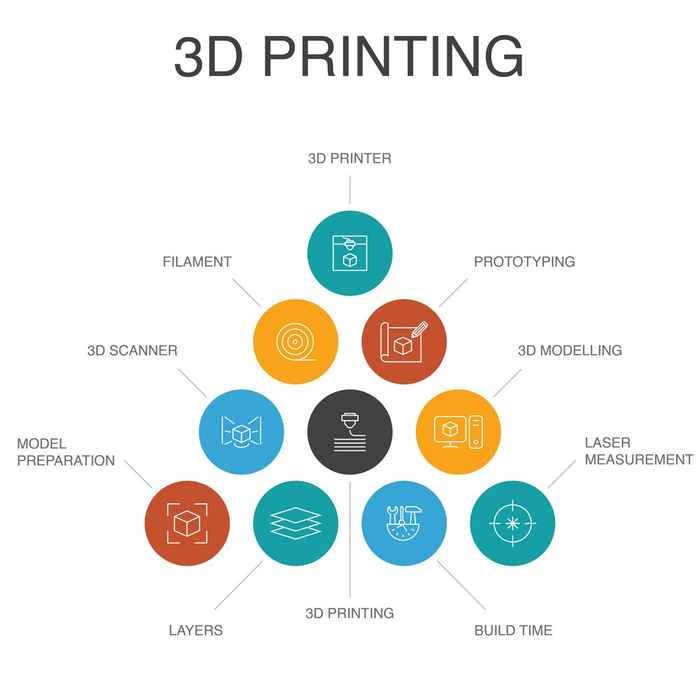
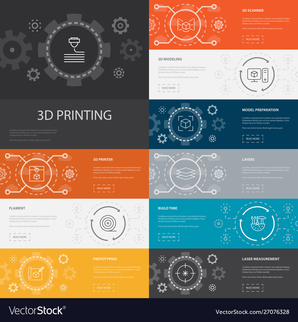
WHAT IS 3D PRINTING?
3D printing is an additive manufacturing technique that works by adding material layer by layer, unlike conventional machining (milling machines for examples) where materials is removed from a stock item (subtractive manufacturing) 3D printing makes it possible to make common objects, spare parts or prototypes for testing. The starting point is a computer file representing the object in three dimensions, broken down into slices. This information is sent to a 3D printer that will perform manufacturing by adding successive layers.
How? What are the needed materials for that
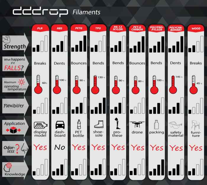
The Filament is the feeded thermoplastic cartridge, into the fused deposition modeling (FDM) 3D printers that makes it possible to print a 3D model. When the right temperature is reached and the material is melted, a 3D print can be started. The fluidity of filament depends on the type of filament and the required extruder- and print bed temperature.
Filament is available in two standard diameters; 1.75 and 2.85 mm/3 mm. There are a wide option when it comes to filament
- Design your digital model using CAD
- Convert your CAD file into SLT
- The slicing
- Printing
- Removing the finished parts from the printer
- Post Processing Stuff
You can also check this “The Book ‘Additive Manufacturing Technologies: Rapid Prototyping to Direct Digital Manufacturing”
Groupe Assignement
Here's the direct link for this part of the assignment
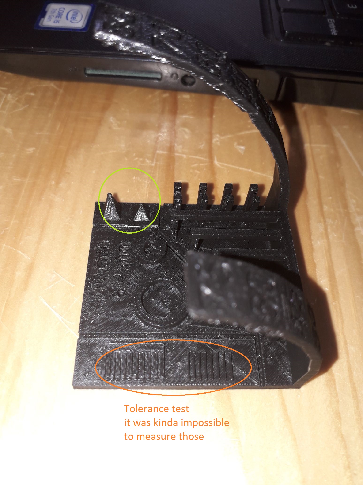
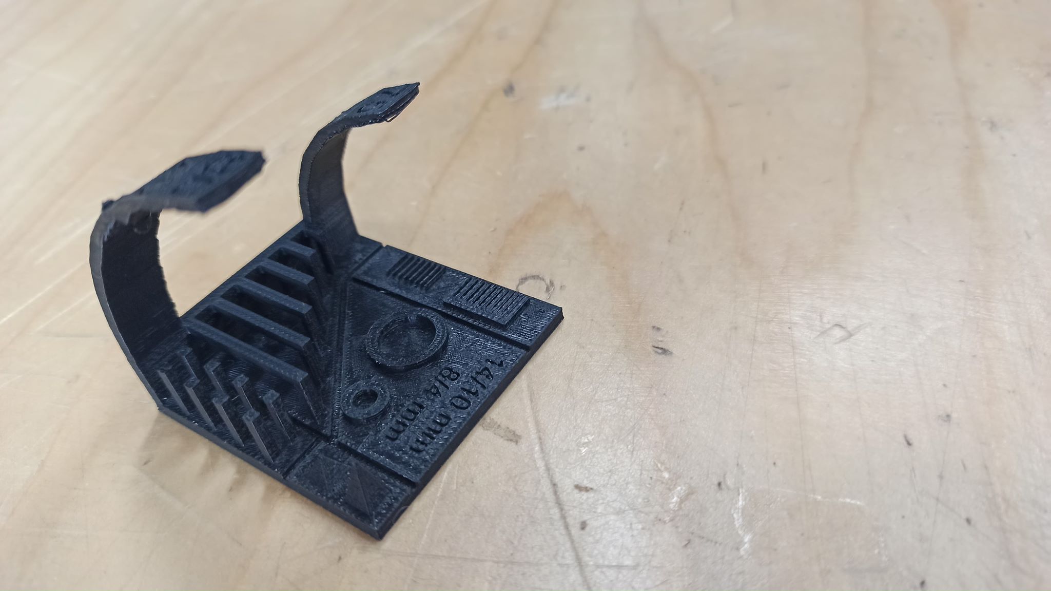
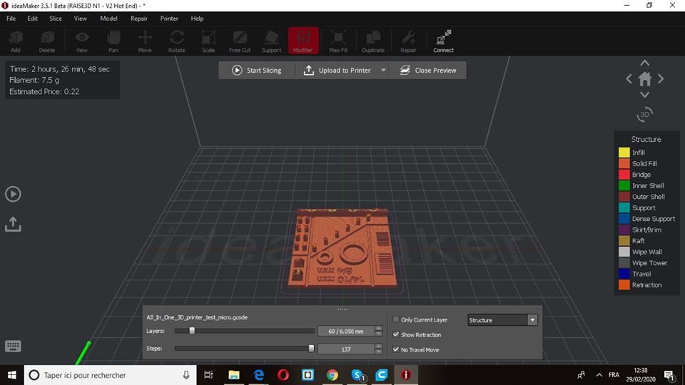
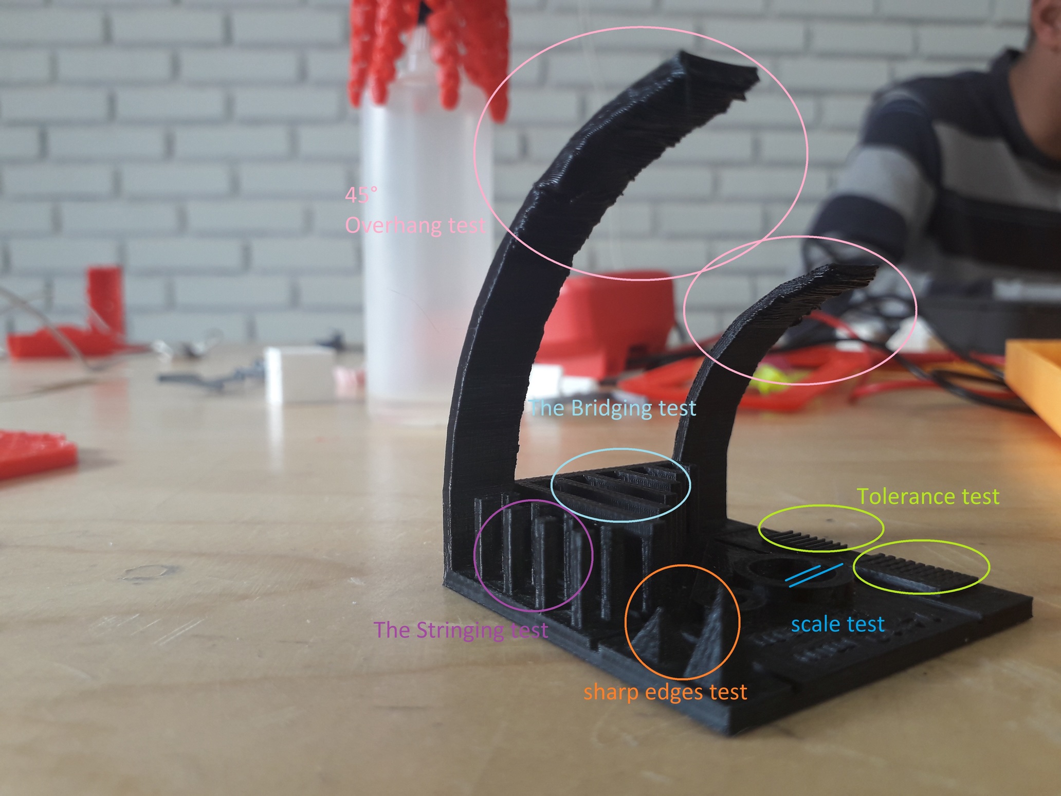
Testing the 3D printerWe have found online a 3D printing model test template or as it’s called, a torture test (seriously, I didn’t even know that this kind of tests is called like that), that can do the job perfectly.
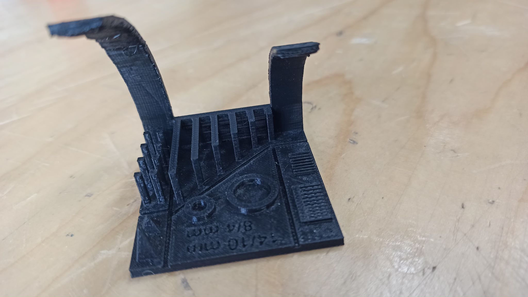
It allowed us to make different tests in one shot; an overhang test, bridging test, stringing test,sharp-corner test, tolerance test, and scale test
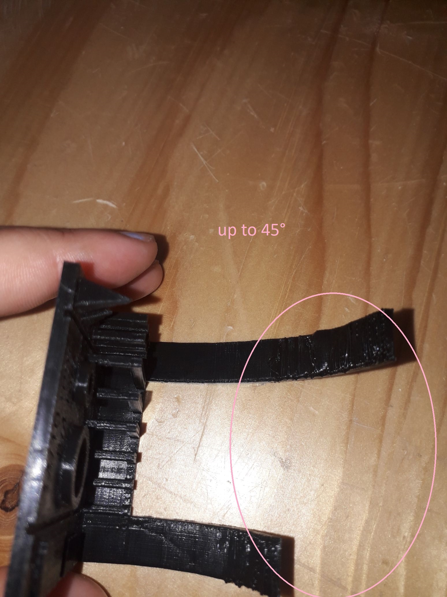
The Overhang :This test allows you to know to which angle our printer can print without the need of a support !
Usually, overhangs up to 45° can still be printed without loss of quality. That’s because any layer in a 45° overhang is mostly supported by the layer beneath. In other words, each new layer has enough support to remain intact and to make printing possible. However, anything past 45 ° approaches the horizontal and becomes difficult to print. Such overhangs are prone to curling, sagging, delamination, or collapsing. Exceeding 45 degrees means every new layer has less of the previous layer to bond with. This translates to a poor quality print with droopy filament strands.
What we got: starting from 45° the quality of the printing started to get so saggy
The Bridging test:Bridging is the printer's ability to print a layer between gaps in lower layers without support, essentially printing over thin air, creating a "bridge". It is very important that your printer can properly bridge, because many prints require some bridging.
What we got: the quality of the bridges looked perfect
The Stringing test:Is when a print has small hairs or in extreme cases thick lines of the filament in between the outside perimeter of two print locations. The two major factors affecting stringing are Retraction and Temperature. Too high of a Temperature would cause a host of other issues in your prints so if you are mainly just experiencing stringing then Retraction is probably your issue.
What we got: the same goes for this part too, there were nothing to complain about !!
The Sharp-corner test:This allows you to test the capability of your printer to make sharp edges without fail.
What we got: the pyramids had a partially narrow edges
Tolerance test:This thing allows you to test the accuracy of your printing process and to determine the optimal clearance between moving parts (e.g. hinges).
What we got: this part was practically impossible to do it 'cause of the tiny measurement there 0.05~0.5
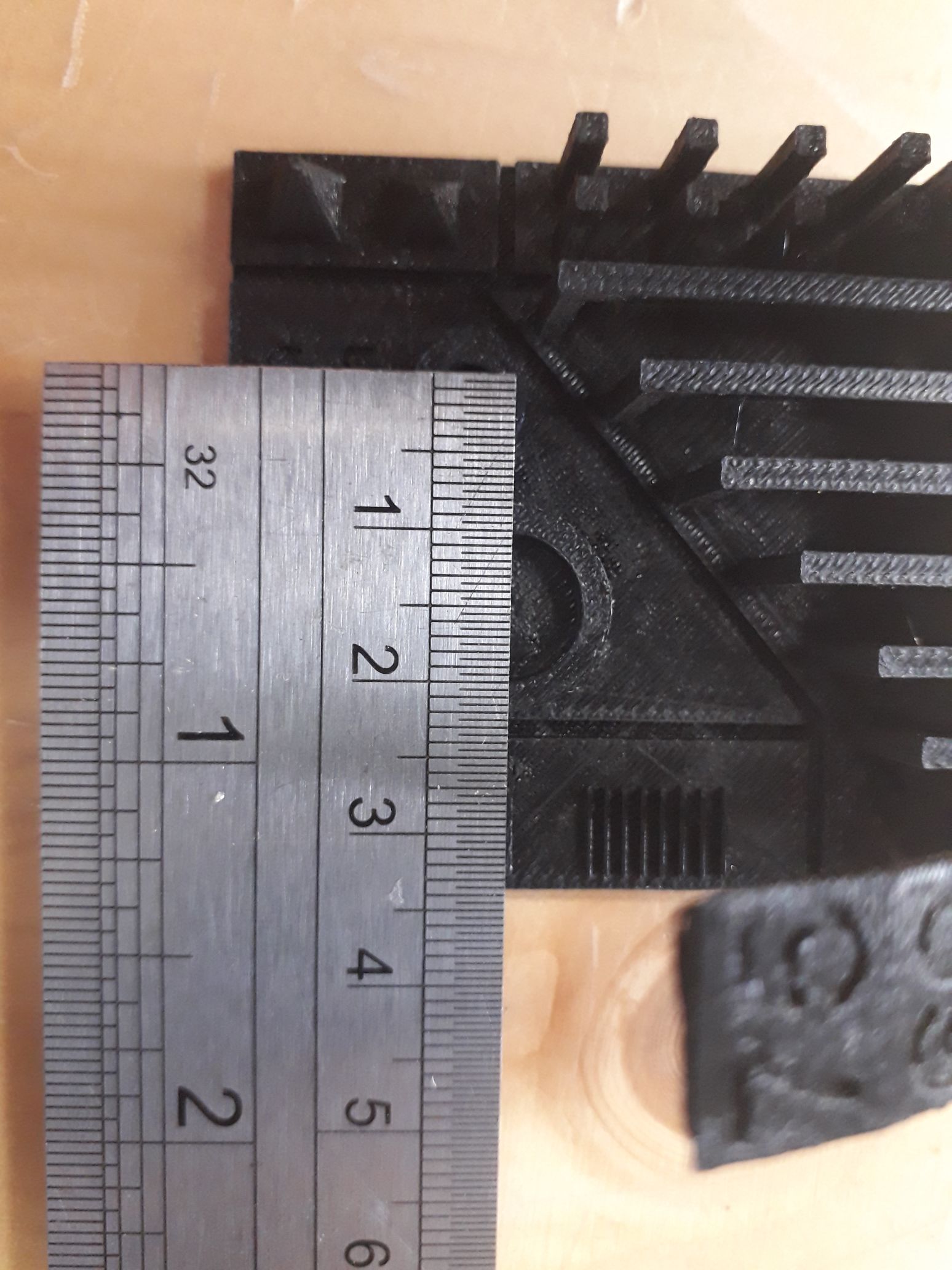
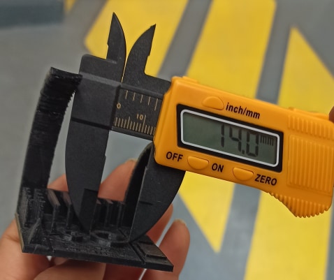
The Scale test:To see how closely a final 3D printed part measures can be, compared to its digital model.
What we got: The diametre of both circles were compatible with
What we used?
The hardware
For the printers, we had three printers to choose from
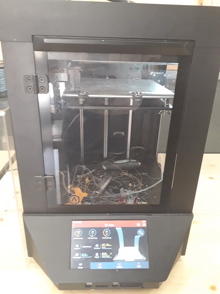
Option 1: Raise3D N1
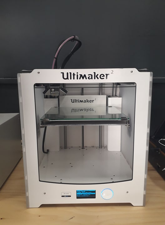
Option 2: Multimaker
Option 3: Anet A8
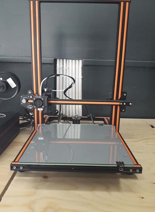
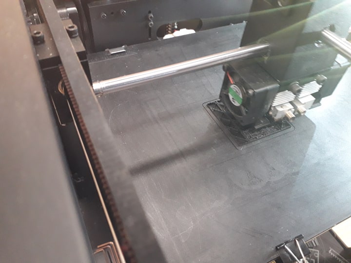
However, we worked with Raise3D N1
- Print technology: FDM (FFF)
- Build Volume (WxDxH):8x8x8 inch/205x205x205
- Layer Resolution:0.01-0.25mm
- Filament Type: PLA/PLA+/ABS/PC/PETG/R-flex/TPU/HIPS/Bronze-filled/wood-filled
- Printing Surface : Buildtak
- Enclosure: Yes
- Nozzle Diameter: 0.4 mm(0.016 in)
- NozzleWorking Temperature:170-300°C
- Number of Nozzles: 1 (standard)/2(otional)
- Printing Speed: 10~150 mm/s
- Positioning Accuracy: XY-axes:0.0125 mm, Z-axis: 0.00125 mm
And let me say, it's hella easy to work with
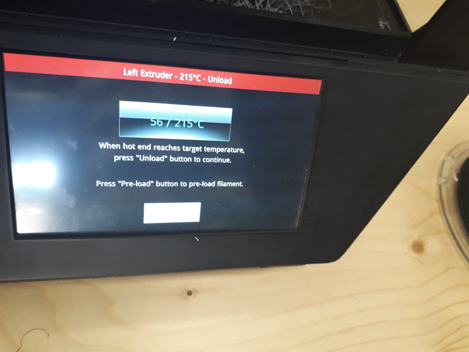
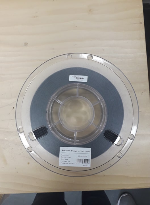
we used the PLA
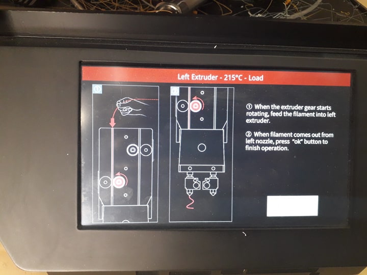
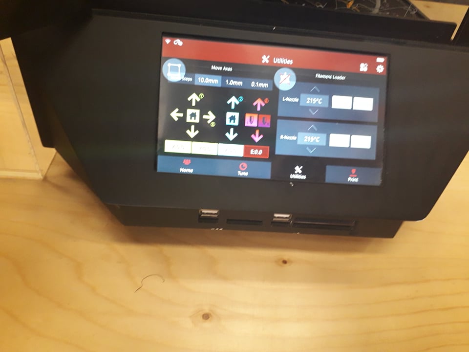
we can change any thing manually
This printer has dual Extruder
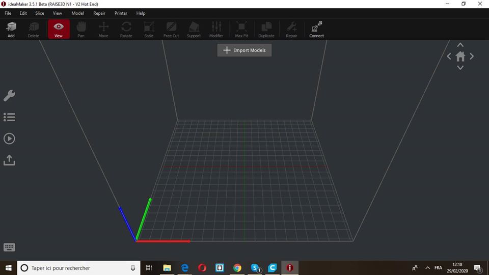
The Software
For this Printing to be done, after downloading the test template as a SLT format, it's the time for the slicing software for the printing process to be done.
For this process, we used a compatible slicing software that called ideaMaker, which is an intuitive slicing software that allows the user to save their select profiles.
- Slicing Software:ideaMaker(supplied free, Simplify3D)
- Supported File types: .stl, .obj
- Supported OS: Windows XPand later versions, mac, linux
- Machine Code Type: G-code
Preparing the test model
Step1: Open the software
Step2: choose your model file
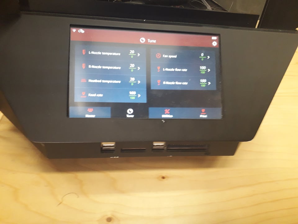
Since we downloaded the Template test as a SLT file, we only had to change some parameters like the infill, the temperture, etc..
Step3: Modify your parameters:
We set the height of the layers to 0.1mm and the first layer height to 0.15mm
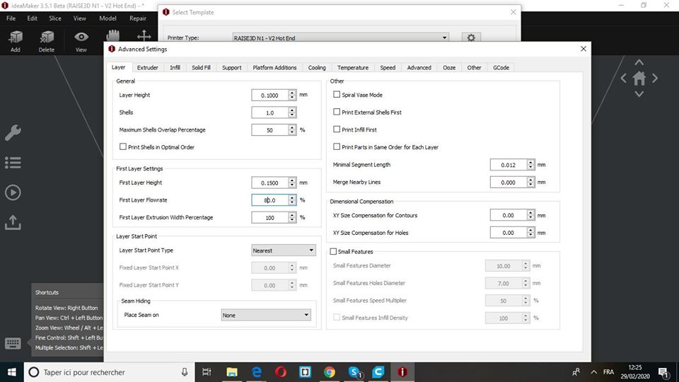
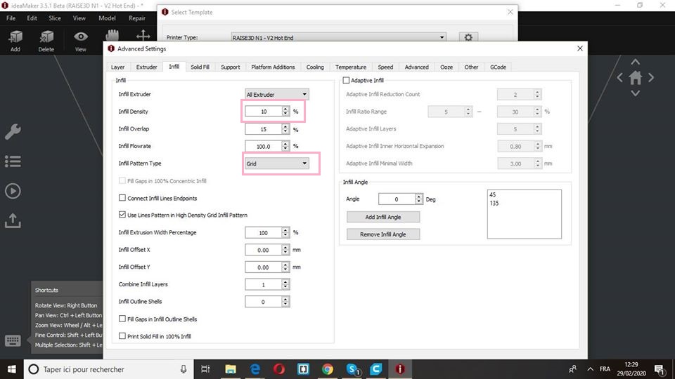
We changed the extrusion width to0.4mm since the Nozzle diameter is 0.4 mm and we modified the infill density to 10% and infill pattern type to Grid!
And finally the Speed parameters!

Overall and as you can see, we changed most of the parameters and have some others par default to have our model printed!!
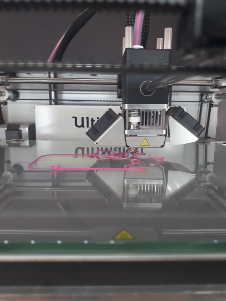
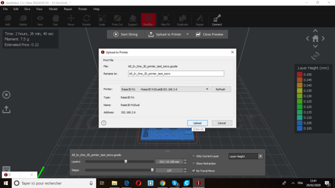
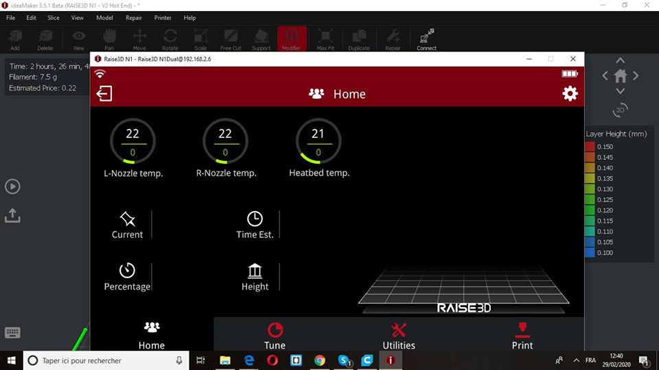
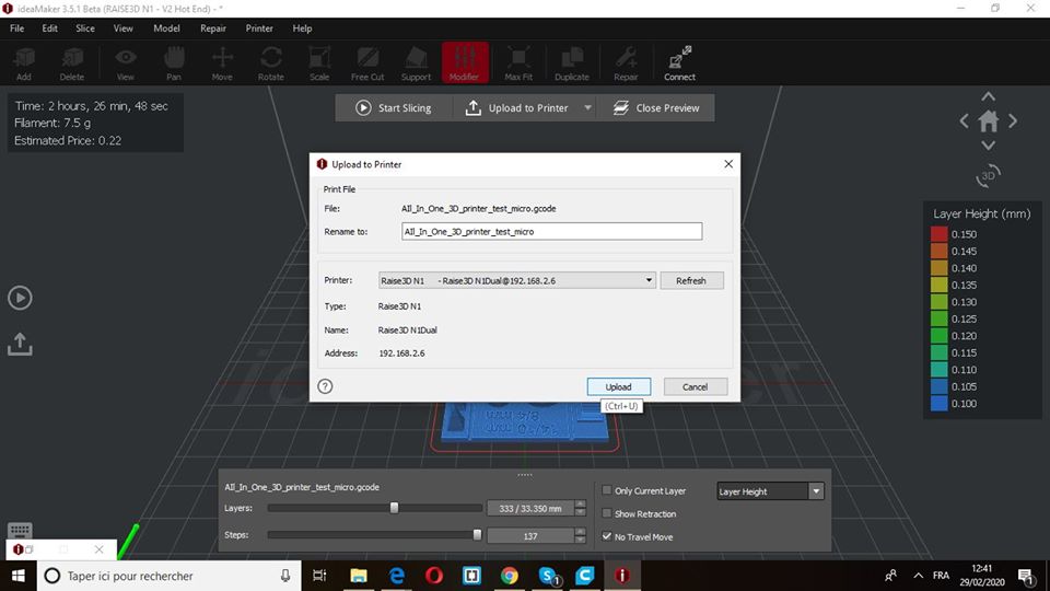
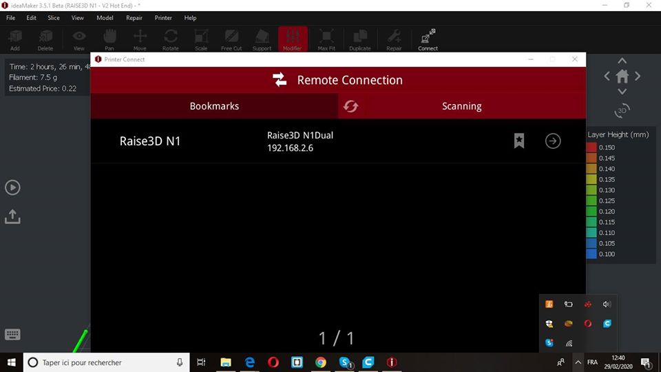
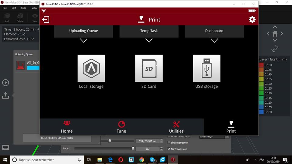
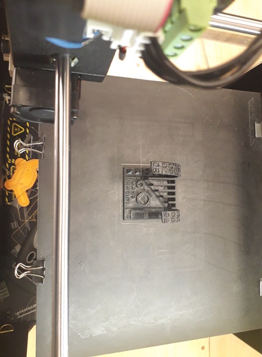
And now the time for the printing:
The good thing about this machine is that we can remotely control it using the software and the Wifi!
.jpg)
we used the PLA filament
we can change any thing manually
This printer has dual Extruder
And TADA, the result
Individual Assignement
Designing a 3D Model and print it with a 3D printer
As what I said previously; there are few steps to follow
- Design your digital model using CAD
- Convert your CAD file into SLT
- The slicing
- Layer height: 0.1mm
- First layer height: 0.15mm
- Infill density: 10%
- Infill pattern: Grid
- Speed: 60mm/s
- Nozzle temperature: 205°c
- Bed temp: 60°c
- Material: PLA
- Printing it
For this step, I used FUSION 360to make a simple model of a plantery (I know, it's so typical to make such model for such assignment, but giving the time and the availability of the materials and machines, I had to make my model as simple as possible)
If you're using FUSION 360, this step is so easy to do; all what you have to is clicking right on the "body" that you want to convert
.png)
As for the slicing, we have to adjust some sittings here like INFILL,THE SPEED, THE TEMPERATURE, etc ~
For this part, I didn't really have that big of work, since I followed what we did in the the group assignment, the same sittings of speed, infill, temperature, etc ...
So in general; these are the sittings that I used for this part of the Assignment:
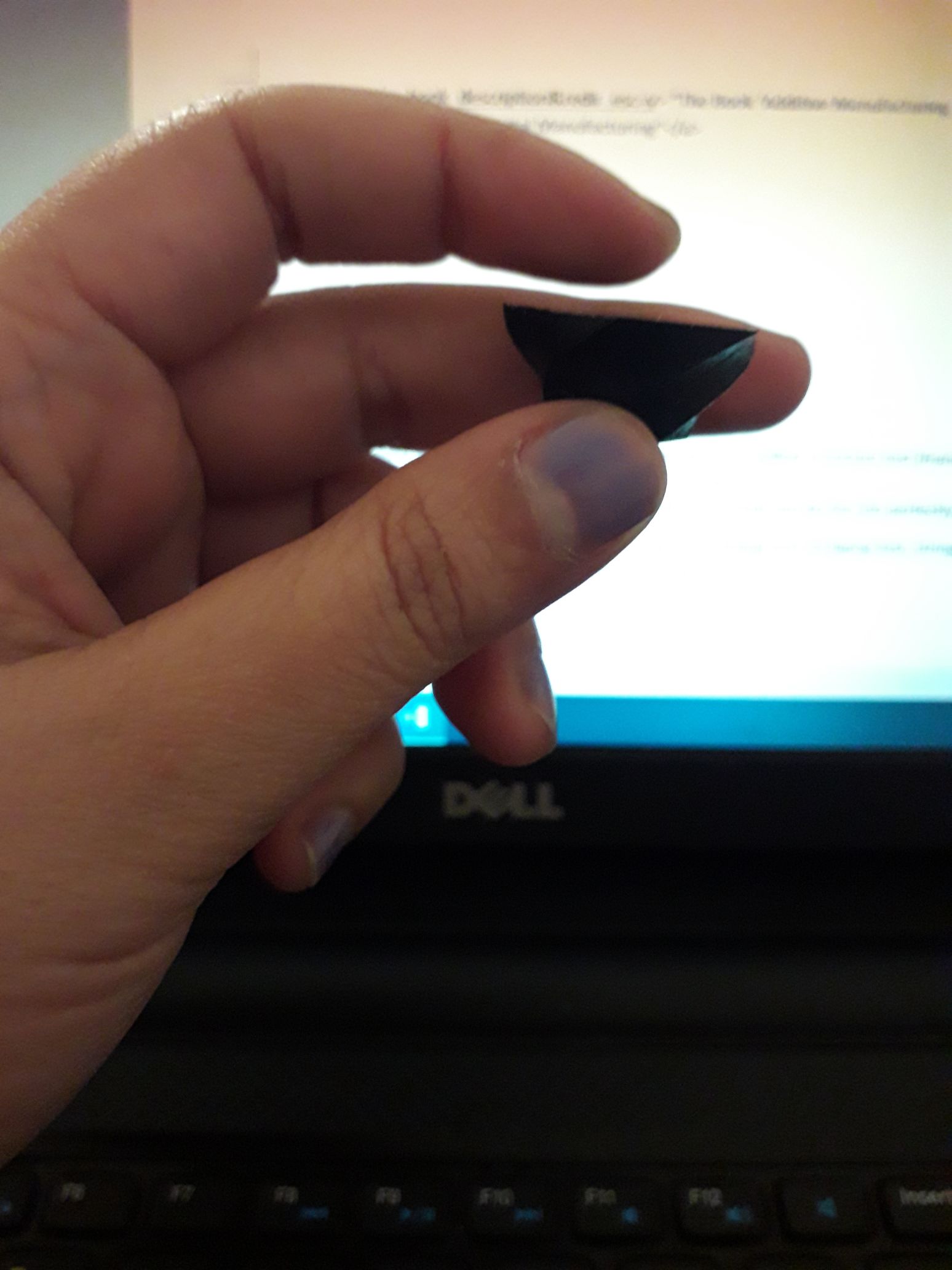
after fixing the sittings on the top, I tried to reduce the size of the printed model up to 40% of the original size!
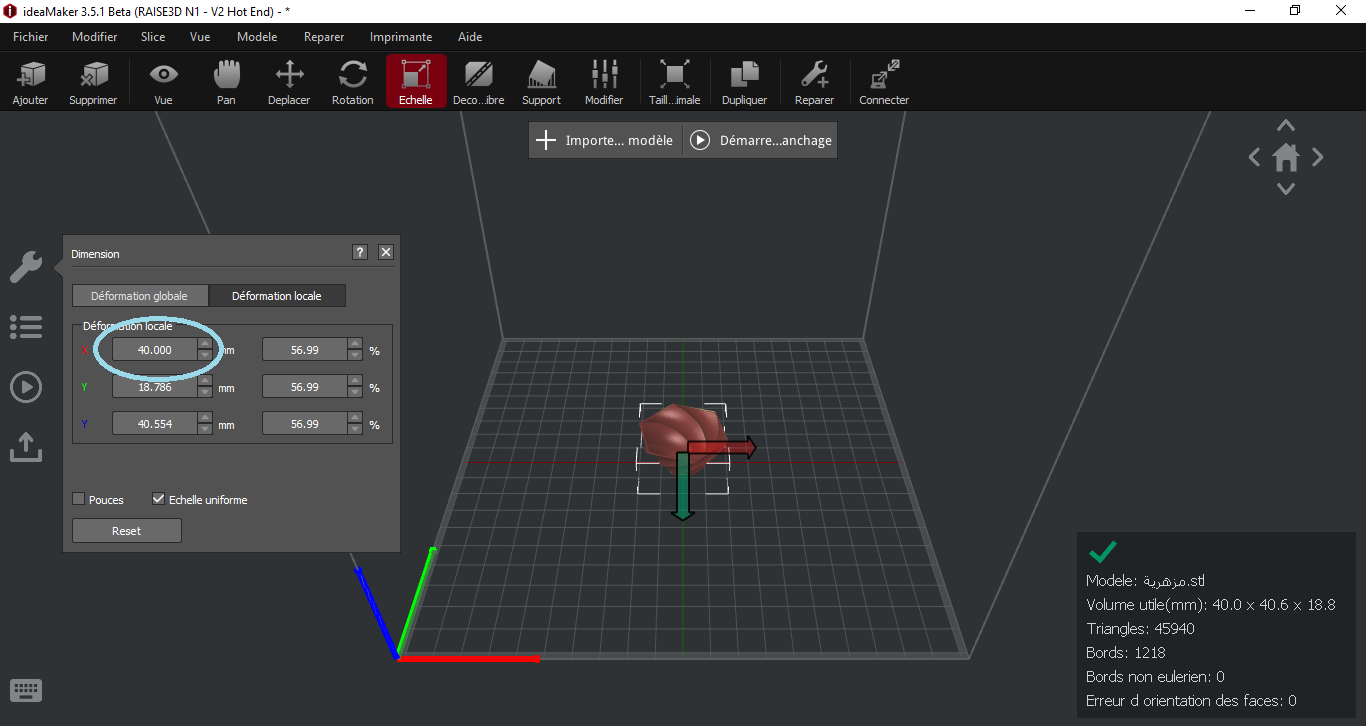
Oops!
I never was expecting this to happen!!xD
though it was so funny to see this!
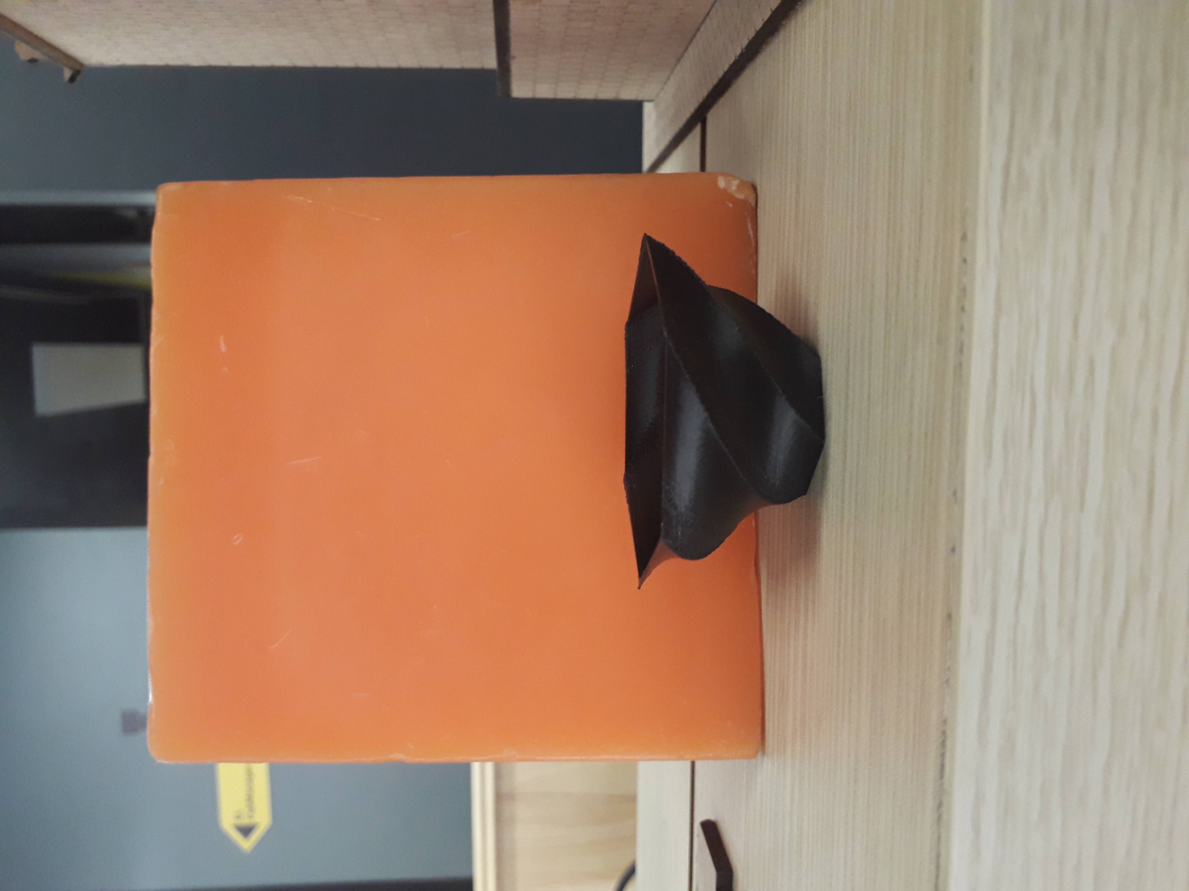
So I tried other measurement, since we had a little time to do the printing: 70%
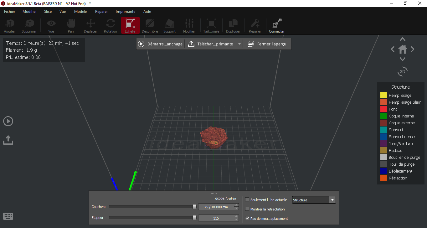
TADA
Scan anything using a 3D scanner
As for this part of the assignment, we had to use a 3d scanner, and use it to scan anything
The hardware
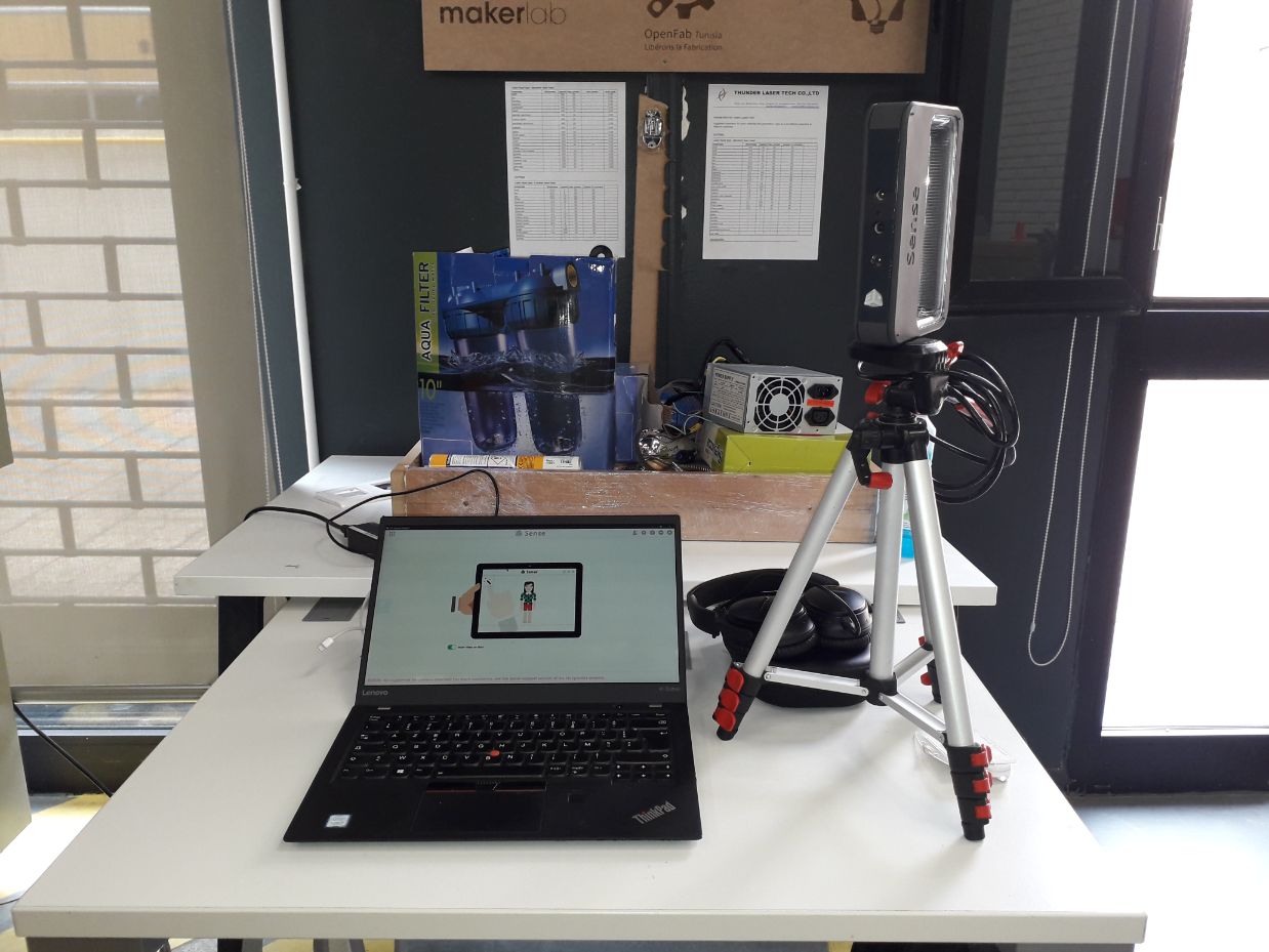
SENSE 2 (REALSENSE SR300) 3D SCANNER;User guide (pdf)//Review
.jpg)
The Software
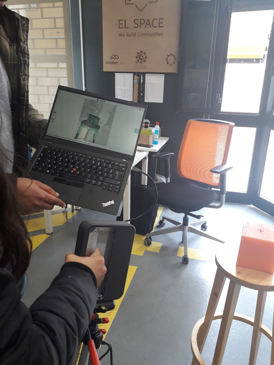
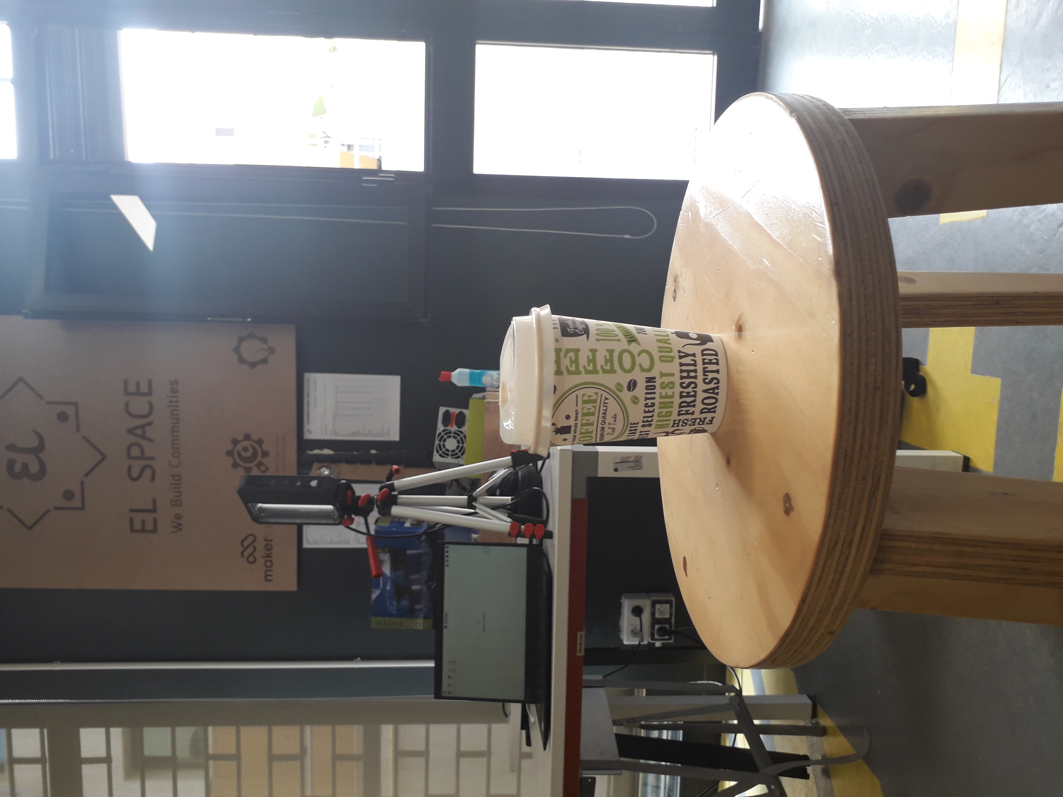
All what we had to to do is putting the target on a fixed spot, and try carefully to move around it with a scanner in one hand and the computer in the other, it seems that there's an alternative way to do the scan, in other words, fixing the scanner and put the "target object" on a turntable and rotate it in front of the scanner
Anyway, we all used the first way :)
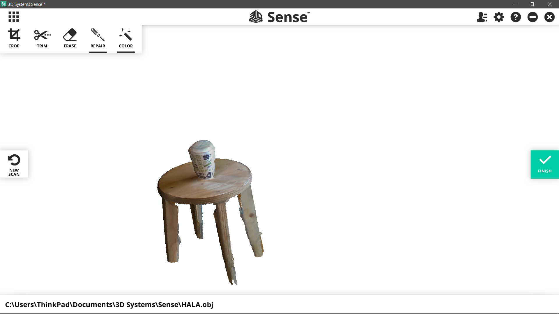
What I got!
PS:
AND TADA